The board
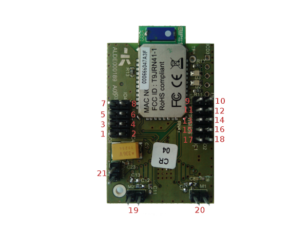
Here is a presentation of the board, and the locations of the different inputs and outputs on it.
Pin repartition
Here is how peripherals are spread over the bluetooth boards:
- 1,2,3,4: Analog inputs
- 5,6,7,8: Digital outputs
- 9,10: servo outputs
- 11,12,14,16,17,18: digital inputs
- 13,15: PWM outputs
- 19,20: motor outputs
- 21: power supply
Board specifications
-
Switching on/off the board:
The board can be switched on/off by a power supply between 4.5 V and 24 V.
Note: if you want to use the motor control outputs, you need to power the board with a minimum voltage of 8 V (this is the H-bridge component's minimum voltage).
-
ADC pins (analog inputs): the voltage of the 4 analog inputs is between 0 V and 3.3 V.
Warning: Overtaking this voltage could damage the board.
-
Digital inputs: all the digital inputs are up to 5 V tolerant.
Warning: Overtaking this voltage could damage the board.
- The four pwm need to be set with values between -32767 and 32767. For the two motor control outputs (pwm1 and pwm2), the sign will determine the sense of rotation.
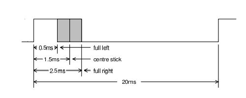
- The servos outputs need to be set with values between 500 and 2500. Those values correspond to the width of the pulses in microseconds (see the following figure for more detailed explaination).
Bluetooth Device
On the board, the large component with an antenna is the bluetooth device. At its right, there are two LEDs. The higher one (D3), is the connection LED. When this LED blinks, it means that the bluetooth device is waiting for connection. The lower LED (D2) is the status LED. When this LED is lit, it means that the bluetooth device is paired with a master.
You can find more information concerning the bluetooth device in the RN-41 user manual.
On the bluetooth device, the sticker (with twelve numbers written on it) is the mac address of the device. You need this address to identify and connect the module to NAO.