Travel limiter
A travel limiter is a (semi-)circular window that is stuck on your transmitter,
to limit how far you can move the cyclic stick into the corner.
Everyone seems to use a circular travel limiter, but here I show that this
is only correct if no exponential is used. When exponential is used, the
shape of the travel limiter has to be adapted to fit the amount of exponential.
We start with the estimated servo deflection f(x,p)- see
my estimation.
Note that this formula is for Futaba FF8s, for other transmitters
the formula and resulting corrected travel limiter may be slightly different.
e-2.5 p x-1
f(x,p)= ----------------
e-2.5 p-1
We now extend this to the two-dimensional case:
g(x,px,y,py) = { f(x,px) ,f(y,py) }
where x is the x-deflection (aileron) and px is the amount of expo for the aileron,
and y is the y-deflection (elevator) and py is the amount of expo for the elevator.
g is a two-vector: a pair of x-servo-deflectio and y-servo-deflection.
Now the total cyclic deflection d will be roughly equivalent to the 'diagonal' of
the two servo deflections, and using pythagoras gives
d(x,px,y,py)=sqrt(f(x,px)2 + f(y,py)2)
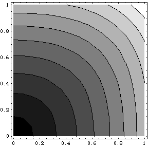
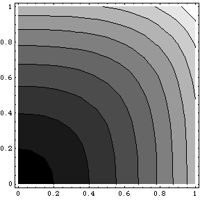
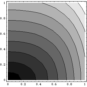
Now we will plot what a 'correct' cyclic travel limiter looks like when using expo. If no exponential is used (0% in all directions), the limiter will be circular. The most usual exponential for the cyclic is to make the cyclic less sensitive around the midpoint, allowing more accurate hovering while not restricting the maximum roll rates. For Futaba this calls for negative values for the expo, on JR I heard that this calls for positive values. When such expo is used the circle of the limiter window has to be stretched towards the corners as in the pictures.


| Corrected shape of travel limiter with -30% expo. The center of the stick is in the left bottom, full right aileron is at right bottom, and full forward elevator at left top. The iso-deflection lines show stick positions that result in equal cyclic deflection. | Idem, but with -50% expo. |
For positive exponential the corners would have to be pulled towards the middle as in this figure:

And of course you can think of combinations:

Another unexpected effect I found is that the aileron and elevator have different travel distances to full stick deflection. The aileron travel is about 1mm longer than the elevator travel. To compensate for this, the cyclic travel limiter would have to be slightly elliptic as well. However this difference can also be compensated with the ATV, assuming the radio first electronically limits the travel and then apply expo (and not first apply expo and then limit the travel).
When using exponential on the cyclic, a travel limiter has to be non-circular
if the maximum roll rates are to be reached also in the corner.
With a circular travel limiter and negative expo, roll rates will be a lot lower in the corner
(when using both aileron and elevator simultaneously) than with pure aileron or pure elevator.
We derived the formulas, and plotted figures showing how the correct shape of the
travel limiter depends on the amount of exponential.