LiPo Batteries
A standard NiCd receiver pack is insufficient when you use digital servos.
A machine equipped with digital servos on all controls will draw 1.5 or maybe even 2 amps
on average (see my servo documentation for details).
A 1700 NiCd pack has an effective capacity of about 1000mAh,
and thus will last about half an hour of flying (2 or 3 flights).
After that, the voltage on the pack
will have dropped to far for enjoyable flying.
To improve this, I switched to a regulated 2800mAh Lithium Polymer pack.
I had only limited space on top of my tank, in fact barely more than the space needed for the 1700 NiCd pack, so the pack had to stay small. Therefore I decided to use 8 700-cells: 2 in series of 4 in parallel, or 2S4P.
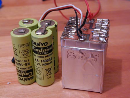
| Size comparison. On the left standard 4.8V/1700 NiCd pack (actually this shows my old 1400pack, but the 1700s look exactly the same). On the right the 7.2V/2800mAh LiPo pack. |
Some more comparison details: the NiCd pack cells weigh 4x36g=144g, the LiPo pack 8x14.9=119.2g Same width and height, 4.4mm (13%) deeper, 17% lighter and 147% extra energy! Size 38x34x54mm, giving 10.7Wh in 0.07liters or 152Wh/l. Okay it's a bit more expensive too ;-)
There are two common ways to make a pack of LiPo cells:
joining them using a printed circuit board (PCB) or joining them with wires.
The first method claims to give extra rigidity to the pack, while the second
method claims to be more crash proof because the batteries have some way to move
around.
There are some webpages on the internet showing how to do a wiring job,
for instance the aht website
or here.
However I decided to use the PCB approach because the wire approach
seemed to use a little more space, resulting in a larger pack,
and because I felt uneasy about soldering 16 wires to loose hanging lips on these cells.
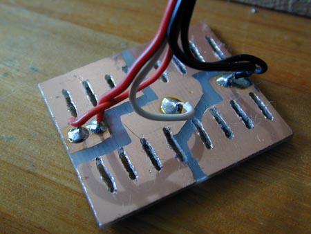
The figures show the PCB that connects the cells in the pack.
I have a separate wire connection the point between the two 4P cells,
enabling to charge both 4P cells separately. This ensures the cells keep
balanced and avoids all risks with overvoltage during charging
which can cause dangerous situations with LiPo cells.
| PCB schema. Copper in yellow. Grey is where the lips of the LiPo cells were planned to be folded down. Black lines are where slits are to be made. | The etched board. Separate white wire for charging and checking the two halves in the cell. |
There was a surprise when I tried to solder the lipo packs in place.
There showed to be two lips at the plus side,
and no one on the internet could tell me what that ment and which lip should be soldered.
When I had made the PCB and tried to solder the first long lip, it showed that
it could not be soldered. Only the outside of the short lip could be soldered. Unfortunately the outside of the short lip (the bottom as in the figure) was exactly
the opposite side of where I had planned to solder the lip to the PCB.
I asked around for aluminium solder, but some people indicated that
aluminium solder has quite high resistance. That seemed not a good idea for a battery pack
so I did not try that. Then I tried some special silver glue to glue the lips to the copper.
The resistance showed very low, but the connection did not feel very strong and I
did not trust this for the vibrating environment of a helicopter.
Flipping the pack around will not help, the wrong side will stay down. Folding the lips the
other way round would cause the lips to fall above the next pack in the row,
which would cause the PCB to stick out above the last pack...
To solve this problem, I finally soldered an extension to these lips.
The extension I used is made from short pieces of
solid copper wire used for wiring 220V power sockets. I folded the short lip around it
(after plugging it into the PCB) and had some solder flow between copper and lip.
I cut off the long useless aluminium lip before soldering.
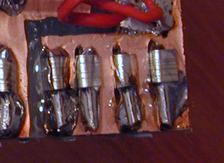
| Note the two lips at the plus side; only the bottom side of the lower one can be soldered. | Lip extensions, needed because the planned folding of the short lips made the unsolderable side of the lip touch the PCB. As you can see the outside of the lips still is perfectly clean of solder. |
A few tips:
1. don't bake the lips too long, 10 seconds should be sufficient.
2. Be careful not to make shortcircuits with all the open copper around.
Tape off all copper parts not relevant for the current soldering.
3. Have a cottonstick soaked in water ready to quickly cool down the lip after
soldering. Don't know if it's important but I thought it would help.
LiPo cells can damage if their voltage goes below 2.5V, even for a short time.
The common accepted minimum average voltage during flight is 3.0V.
This seems to be the cutoff point for high-discharge rates, so probably
my low-discharge application could use a lower cutoff point, but I prefer to stay
on the safe side. The voltage goes down very rapidly when past the 3.0V point anyway.
Reading off the available capacity at cutoff at 3.0V from the discharge table below
(the table is for two cells in series; click on it for larger view or
enlarge your window) shows
that we have (just over) 14 minutes at 2.8 Amperes, or some 653mAh per cell.
That gives us an effective capacity of 4*653=2613mAh.
As we need about 400mAh per flight (assuming 2A and 12 minutes, pessimistic estimate)
we should be able to get 6 flights from the pack. I expect that will be larger in practice:
assuming 1.5A, I would get 8 (nearly 9) flights. Also, the discharge table assumes a 4C discharge
(2.8A per pack, or an equivalent of 11.2A for my pack), while I will stay below 2A. This should
also give better results.
| Note the two lips at the plus side; only the bottom side of the lower one can be soldered. |
I did a test run with an approximate 1A discharge rate one of the two 4P parts of the pack
(fixed 3.9ohm 5W resistor).
Indeed the theoretical capacity is reached, and more: I discharged to only 3.0V
(instead of the minimal 2.5V), and that gave 2961mAh or 10.7Wh.
This is 740mAh per cell which is more than specified, which must be because I'm discharging
at a much lower than peak rate.
But a more important result was the shape of the discharge curve. At low discharge rates,
the pack voltage stays high a lot longer, and the dropoff at the end becomes much steeper.
This means that you need extra safety margin in terms of minimum voltage at the
start of the flight.
Remember that the curves below are a 1A-LOADED voltage (0.25A per cell) for the eTec 700 cells.
If the cell had time to recover, you may need to load
the pack up to 4 minutes (@1A=250mA per cell) before reading the correct loaded voltage, if you read earlier than
that the reading will be up to 0.04V too optimistic.
| Voltage against time, discharge over 3.9 Ohm. 4x700pack |
| capacity (mAh) against voltage, 3.9Ohm load. 4x700pack | capacity (Wh) against voltage, 3.9Ohm load.4x700pack |
After more than 100 flights I re-checked the pack. The capacity is still the same as when it was new: 2948mAh and 10.5Wh. The pack seems to have even survived an overdischarge: during one check I accidentally discharged to 2.35V, well below the minimum of 2.5V.
| capacity (mAh) against voltage after >100 flights, 3.9Ohm load. 4x700pack. |
A bit off-topic but interesting: as large as the capacity improvement may look,
it's interesting to look at the current
state of the art in non-rechargable cells to see what the future will bring
(for rechargable batteries).
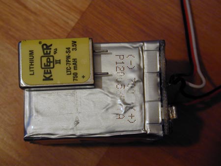
The picture below shows a Lithium Thionyl Chloride cell. It has
a little bit more capacity and the same voltage
as the e-Tec LiPo 700 cell behind it, but it's only a quarter of that size
and only 6.8grams!
The pack is working as expected. The result looks good and is stiff.
Theoretical capacity accurately predicts actual capacity.
In practice I can easily do 7 flights with a few heavy 3D stuff and a bit hovering,
and after that there is still plenty left (more than 1300mAh).
Thus, it is doing a great job, stable flying for 8 flights without any problems.
A little sidemark on the soldering, if I would have to make another pack
I probably would try the wire approach.
I discovered too late that one of the lipo soldering lips can be soldered
only at one side.
Making the print and soldering was quite a hassle.
Also, if short wires are used the result could be as thinner than
the print plus the lip extension that I have now.