Difference between revisions of "VRET physiological"
| Line 4: | Line 4: | ||
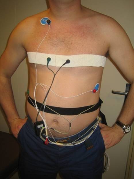
The figure below shows how to connect the pads for a heart rate measurement. | The figure below shows how to connect the pads for a heart rate measurement. | ||
The green ground pad is in the one corner, the red and black sensors "1" are diagonally placed wide apart, on the chest. The exact position is not so relevant. | The green ground pad is in the one corner, the red and black sensors "1" are diagonally placed wide apart, on the chest. The exact position is not so relevant. | ||
| + | |||
[[Image:Heartmeas.jpg]] | [[Image:Heartmeas.jpg]] | ||
| + | |||
Figure. Pads configured for heart rate measurement | Figure. Pads configured for heart rate measurement | ||
[[Image:Physiological.jpg]] | [[Image:Physiological.jpg]] | ||
Revision as of 12:10, 24 June 2009
Attaching the electrodes
The figure below shows how to connect the pads for a heart rate measurement.
The green ground pad is in the one corner, the red and black sensors "1" are diagonally placed wide apart, on the chest. The exact position is not so relevant.
Figure. Pads configured for heart rate measurement

